No Current Sellers for LeCroy 735Zi-A
Sign Up/Login to get notified when someone has one for sale.
Manufacturer: LeCroy
Model: 735Zi-A
Description:
3.5 GHz, 20 GS/s, 4ch, 32 Mpts/Ch DDA with 15.4" WXGA Color Display. 50 ohm and 1 Mohm Input. 40 GS/s and 64 Mpts/Ch in interleaved mode.
Sign Up/Login to get notified when someone has one for sale.
3.5 GHz, 20 GS/s, 4ch, 32 Mpts/Ch DDA with 15.4" WXGA Color Display. 50 ohm and 1 Mohm Input. 40 GS/s and 64 Mpts/Ch in interleaved mode.
Vertical System |
|
| Analog Bandwidth (Max) | 3.5 GHz |
| Analog Bandwidth @ 50 Ω (-3 dB) (ProBus Input) | 3.5 GHz (≥10 mV/div) |
| Analog Bandwidth @ 1 MΩ (-3 dB) (ProBus Input) | 500 MHz (typical) (≥5 mV/div) |
| Rise Time (10-90%, 50 Ω) | 120ps (typical, flatness mode) |
| Rise Time (20-80%, 50 Ω) | 90ps (typical, flatness mode) |
| Input Channels | 4 |
| Bandwidth Limiters | 20 MHz, 200 MHz, 1 GHz, 3 GHz |
| Input Impedance | 50 Ω+/-2% or 1 MΩ||16pF, 10 MΩ || 11 pF with supplied Probe |
| Input Coupling | ProBus Inputs - 1 MΩ: AC, DC, GND; 50 Ω: DC, GND |
| Maximum Input Voltage | 50 Ω: ±5 Vrms 1 MΩ: 250 V max. (peak AC: < 10 kHz + DC) |
| Channel-Channel Isolation | DC to 2 GHz: 46 dB (>200:1) 2 to 4 GHz: 34 dB (>50:1) 4 to 6 GHz: 26 dB (>20:1) (For any two ProLink input channels, same v/div settings, typical) |
| Vertical Resolution | 8 bits; up to 11 bits with enhanced resolution (ERES) |
| Sensitivity | 50 Ω: 2 mV-1 V/div, fully variable (2-9.99 mV/div via zoom); 1 MΩ: 1 mV-10 V/div, fully variable |
| DC Vertical Gain Accuracy (Gain Component of DC Accuracy) | ±1% F.S. (typical), offset at 0V; ±1.5% F.S. (test limit), offset at 0V |
| Vertical Noise Floor (50 mV/div) | 1.30 mVrms (typical) |
| Offset Range | 50 Ω (ProBus) ±750 mV @ 10 mV - 170 mV/div ±4 V @ 172 mV - 1 V/div 1 MΩ ±1 V @ 2 mV - 128 mV/div ±10 V @ 130 mV - 1.28 V/div ±100 V @ 1.3 V - 10 V/div |
| DC Vertical Offset Accuracy | ±(1.5% of offset setting + 1.5% F.S. + 1 mV) (typical) ±(1.5% of offset setting + 2.5% F.S. + 2 mV) (test limit) |
Horizontal System |
|
| Timebases | Internal timebase common to 4 input channels; an external clock may be applied at the auxiliary input |
| Time/Division Range | 20 ps/div-3200 s/div (Real-Time Mode: 20 ps/div - 2000 s/div; RIS mode: 20 ps/div - 10 ns/div, user selectable at ≤10ns/div; Roll mode: 100 ms/div up to 3200 s/div, user selectable at ≥100 ms/div and ≤5 MS/s), depending on memory length |
| Clock Accuracy | < 1 ppm + (aging of 0.5ppm/yr from last calibration) |
| Sample Clock Jitter | up to 10µs Acquired Time Range: 100fsrms (Internal Timebase Reference) up to 3.2ms Acquired Time Range: 150fsrms (Internal Timebase Reference) |
| Delta Time Measurement Accuracy | √2*√((Noise/SlewRate)^2+(Sample Clock Jitter)^2 ) (RMS)+(clock accuracy*reading)(seconds) |
| Jitter Measurement Floor | √((Noise/SlewRate)^2+(Sample Clock Jitter)^2 ) secondsrms (TIE) |
| Jitter Noise Floor | 800 fs (TIE, typical) |
| Jitter Between Channels | <560fsrms (TIE, typical, measured at maximum bandwidth) |
| Trigger and Interpolator Jitter | ≤ 2 ps RMS (typical) <0.1 ps RMS (typical, software assisted) |
| Channel-Channel Deskew Range | ±9 x time/div. setting, 100 ms max., each channel |
| External Timebase Reference (Input) | 10 MHz; 50 Ω impedance, applied at the rear input |
| External Timebase Reference (Output) | 10 MHz; 50 Ω impedance, output at the rear |
| External Clock | 30 MHz-2 GHz, 50 Ω impedance, applied at the auxiliary input |
Acquisition System |
|
| Single-Shot Sample Rate/Ch | 40 GS/s on 2 Ch 20 GS/s on 4 Ch |
| Random Interleaved Sampling (RIS) | 200 GS/s for repetitive signals (20 ps/div to 10 ns/div) |
| Maximum Trigger Rate | 1,000,000 waveforms/second (in Sequence Mode, up to 4 channels) |
| Intersegment Time | 1 µs |
| Standard Memory (4 Ch / 2 Ch / 1Ch) (Number of Segments) | 20M / 40M / 40M (4,500) |
| Memory Options (4 Ch / 2 Ch / 1Ch) (Number of Segments) |
S-32 Option: 32M / 64M / 64M (15,000) M-64 Option: 64M / 128M / 128M (15,000) L-128 Option: 128M / 256M / 256M (15,000) |
Acquisition Processing |
|
| Averaging | Summed averaging to 1 million sweeps; continuous averaging to 1 million sweeps |
| Enhanced Resolution (ERES) | From 8.5 to 11 bits vertical resolution |
| Envelope (Extrema) | Envelope, floor, or roof for up to 1 million sweeps |
| Interpolation | Linear or Sin x/x |
Triggering System |
|
| Modes | Normal, Auto, Single, and Stop |
| Sources | Any input channel, Aux, Aux/10, or line; slope and level unique to each source (except line trigger) |
| Coupling Mode | DC, AC, HFRej, LFRej |
| Pre-trigger Delay | 0-100% of memory size (adjustable in 1% increments of 100 ns) |
| Post-trigger Delay | 0-10,000 divisions in real time mode, limited at slower time/div settings or in roll mode |
| Hold-off by Time or Events | From 2 ns up to 20 s or from 1 to 99,999,999 events |
| Internal Trigger Range | ±4.1 div from center (typical) |
| Trigger Sensitivity with Edge Trigger ProBus Inputs | 2 div @ < 3.5 GHz 1.5 div @ < 1.75 GHz 1.0 div @ < 200 MHz (for DC, AC, LFRej coupling, ≥ 10 mV/div, 50 Ω ) |
| External Trigger Sensitivity, (Edge Trigger) | 2 div @ < 1 GHz 1.5 div @ < 500 MHz 1.0 div @ < 200 MHz (for DC, AC, LFRej coupling) |
| Max. Trigger Frequency, SMART Trigger | 2.0 GHz @ ≥ 10 mV/div (minimum triggerable width 250 ps) |
| External Trigger Input Range | Aux (±0.4 V); Aux/10 (±4 V) |
Basic Triggers |
|
| Edge | Triggers when signal meets slope (positive, negative, or either) and level condition. |
| Window | Triggers when signal exits a window defined by adjustable thresholds |
| TV-Composite Video | Triggers NTSC or PAL with selectable line and field; HDTV (720p, 1080i, 1080p) with selectable frame rate (50 or 60 Hz) and Line; or CUSTOM with selectable Fields (1-8), Lines (up to 2000), Frame Rates (25, 30, 50, or 60 Hz), Interlacing (1:1, 2:1, 4:1, 8:1), or Synch Pulse Slope (Positive or Negative). |
SMART Triggers |
|
| State or Edge Qualified | Triggers on any input source only if a defined state or edge occurred on another input source. Delay between sources is selectable by time or events. |
| Qualified First | In Sequence acquisition mode, triggers repeatably on event B only if a defined pattern, state, or edge (event A) is satisfied in the first segment of the acquisition. Holdoff between sources is selectable by time or events. |
| Dropout | Triggers if signal drops out for longer than selected time between 1 ns and 20 s. |
| Pattern | Logic combination (AND, NAND, OR, NOR) of 5 inputs (4 channels and external trigger input). Each source can be high, low, or don't care. The High and Low level can be selected independently. Triggers at start or end of the pattern. |
SMART Triggers with Exclusion Technology |
|
| Glitch | Triggers on positive or negative glitches with widths selectable as low as 500ps (depending on oscilloscope bandwidth) to 20 s, or on intermittent faults. |
| Width (Signal or Pattern) | Triggers on positive, negative, or both widths with widths selectable as low as 500ps (depending on oscilloscope bandwidth) to 20 s, or on intermittent faults. |
| Interval (Signal or Pattern) | Triggers on intervals selectable between 1 ns and 20 s. |
| Timeout (State/Edge Qualified) | Triggers on any source if a given state (or transition edge) has occurred on another source. Delay between sources is 1 ns to 20 s, or 1 to 99,999,999 events. |
| Runt | Trigger on positive or negative runts defined by two voltage limits and two time limits. Select between 1 ns and 20 ns. |
| Slew Rate | Trigger on edge rates. Select limits for dV, dt, and slope. Select edge limits between 1 ns and 20 ns. |
| Exclusion Triggering | Trigger on intermittent faults by specifying the expected behavior and triggering when that condition is not met |
Cascade (Sequence) Triggering |
|
| Capability | Arm on "A" event, then Trigger on "B" event. Or Arm on "A" event, then Qualify on "B" event, and Trigger on "C" event. |
| Types | Cascade A then B: Edge, Window, Pattern (Logic) Width, Glitch, Interval, Dropout, or Measurement. Measurement can be on Stage B only. Cascade A then B then C (Measurement): Edge, Window, Pattern (Logic), Width, Glitch, Interval, Dropout, or Measurement. Measurement can be on Stage C only. Cascade A then B then C: Edge, Window, Pattern (Logic) |
| Holdoff | Holdoff between A and B or B and C is selectable by time (1ns to 20s) or number of events. Measurement trigger selection as the last stage in a Cascade precludes a holdoff setting between the prior stage and the last stage. |
High Speed Serial Protocol Triggering |
|
| Data Rates | (Option WPZi-MSPT) 100 Mb/s - 1.25 Gb/s |
| Pattern Length | 80 bits, NRZ or 8b10b |
| Clock and Data Outputs | 400mVp-p (typical) AC coupled |
| Clock Recovery Jitter | 2 ps rms + 0.3% Unit Interval rms for PRBS data patterns with 50% transition density |
| Hardware Clock Recovery Loop BW | PLL Loop BW = Fbaud/5500, 100 Mb/s to 2.488 Gb/s (typical) |
Low Speed Serial Protocol Triggering (Optional) |
|
| Optionally available | I2C, SPI (SPI, SSPI, SIOP), UART-RS232, CAN, LIN, FlexRay, MIL-STD-1553, AudioBus |
Measurement Trigger |
|
| Measurement Trigger Capability | Select from a large number of measurement parameters trigger on a measurement value with qualified limits. Can be used as only trigger or last event in a Cascade Trigger. |
Color Waveform Display |
|
| Type | Color 15.3" flat panel TFT-Active Matrix LCD with high resolution touch screen |
| Resolution | WXGA; 1280 x 768 pixels. |
| Number of traces | Display a maximum of 16 traces (up to 40 with some software options). Simultaneously display channel, zoom, memory and math traces. |
| Grid Styles | Auto, Single, Dual, Quad, Octal, X-Y, Single+X-Y, Dual+X-Y |
| Waveform Representation | Sample dots joined, or sample dots only |
Internal Waveform Memory |
|
| Internal Waveform Memory | 12 active waveform memory traces (M1-M12) store 16 bit/point full length waveforms. Waveforms can be stored to any number of files limited only by the data storage media capacity. |
Integrated Second Display |
|
| Type | Supports touch screen integration of user-supplied second display with split-grid capability. (Note: touch screen driver for second display may not be a Fujitsu driver) |
| Resolution | Determined by display chosen by user |
LeCroy WaveStream™ Fast Viewing Mode |
|
| Intensity | 256 Intensity Levels, 1-100% adjustable via front panel control |
| Types | Select analog or color-graded |
| Number of Channels | up to 4 simultaneously |
| Max Sampling Rate | 40 GS/s (20 GS/s for WavePro 715Zi without WPZi-1.5GHZ-4X20GS option) |
| Persistence Aging | Select from 500 ms to Infinity |
| Waveforms/second (continuous) | up to 2500 Waveforms/second |
| Operation | Front panel toggle between WaveStream ON (Analog), ON (Color) and OFF |
Analog Persistence Display |
|
| Analog and Color-Graded Persistence | Variable saturation levels; stores each trace's persistence data in memory |
| Persistence Types | Select analog, color, or three-dimensional |
| Trace Selection | Activate persistence on all or any combination of traces |
| Persistence Aging | Select from 500 ms to infinity |
| Sweep Display Modes | All accumulated, or all accumulated with last trace highlighted |
High Speed Digitizer Output (Option) |
|
| Type | LeCroy LSIB |
| Transfer Rate | up to 325 Mpt/s (Maximum) |
| Output Protocol | PCI Express, Gen 1 (4 lanes utilized for data transfer) |
| Control Protocol | TCP/IP |
| Command Set | Via Windows Automation, or via LeCroy Remote Command Set |
Processor/CPU |
|
| Type | Intel® CoreTM i7-2600 Quad, 2.6 GHz (up to 3.8 GHz in Turbo mode) (or better) |
| Processor Memory | 8 GB standard for STD memory (20 Mpt), S-32 and M-64 memory options 16 GB standard for L-128 memory options Up to 32 GB optional |
| Operating System | Microsoft Windows® 7 Professional Edition (64-bit) |
| Real Time Clock | Date and time displayed with waveform in hardcopy files. SNTP support to synchronize to precision internal clocks. |
Zoom Expansion Traces |
|
| Zoom Expansion Traces | Display up to 12 Zoom and 12 Math/Zoom traces |
Setup Storage |
|
| Front Panel and Instrument Status | Store to the internal hard drive, over the network, or to a USB-connected peripheral device. |
Interface |
|
| Remote Control | Via Windows Automation, or via LeCroy Remote Command Set |
| Network Communication Standard | VXI-11 or VICP, LXI Class C (v 1.2) Compliant |
| GPIB Port | Supports IEEE - 488.2 |
| LSIB Port (optional) | Supports PCIe Gen1 x4 protocol with LeCroy supplied API |
| Ethernet Port | Supports 10/100/1000BaseT Ethernet interface (RJ45 port) |
| USB Ports | minimum 6 total (incl. 3 front panel) USB 2.0 ports support Windows compatible devices |
| External Monitor Port | 15 pin D-Type WXGA compatible to support customer-supplied external monitor. Includes support for extended desktop operation with second monitor. |
| Peripheral Bus | LeCroy LBUS standard |
Auxiliary Input |
|
| Signal Types | For External Trigger Input |
| Coupling | 50 Ω: DC; 1 MΩ: AC, DC, GND |
| Max. Input Voltage | 50 Ω: 5 Vrms; 1 MΩ: 250 V (Peak AC < 10 kHz + DC) |
Auxiliary Output |
|
| Signal Types | Select from calibrator, control signals or Off |
| Output Signal | 500 Hz-5 MHz square wave or DC level; 2.5mV to 500 mV into 50 Ω (5 mV-1 V into 1 MΩ) |
| Control Signals | Trigger enabled, trigger out, pass/fail status, off |
| Connector Type | BNC, located on front |
Automatic Setup |
|
| Auto Setup | Automatically sets timebase, trigger, and sensitivity to display a wide range of repetitive signals |
| Find Vertical Scale | Automatically sets the vertical sensitivity and offset for the selected channel to display a waveform with the maximum dynamic range |
General |
|
| Auto Calibration | Ensures specified DC and timing accuracy is maintained for 1 year minimum. |
Probes |
|
| Probes | Qty. (4) ÷10 Passive Probes |
| Probe System | Probus (and ProLink on 4-6 GHz models). Automatically detects and supports a variety of compatible probes |
| Scale Factors | Automatically or manually selected depending on probe used |
| Calibration Output | Cal Output: 1kHz square wave, 1Vp-p (typical), output to probe hook. Fast Edge Output: 5MHz square wave, 450mVp-p (typical), 110ps rise time, output to SMA connector, AC Coupled. |
Power Requirements |
|
| Voltage | 100-240 VAC ±10% at 45-66 Hz; 100-120 VAC ±10% at 380-420 Hz; Automatic AC Voltage Selection; Installation Category 300 V CAT II |
| Max. Power Consumption | 800 W/800 VA |
Environmental and Safety |
|
| Temperature (Operating) | +5 °C to +40 °C including CD-RW/DVD-ROM drive |
| Temperature (Non-Operating) | -20 °C to +60 °C |
| Humidity (Operating) | 5% to 80% relative humidity (non-condensing) up to +31 °C. Upper limit derates to 50% relative humidity (non-condensing) at +40 °C. |
| Humidity (Non-Operating) | 5% to 95% relative humidity (non-condensing) as tested per MIL-PRF-28800F |
| Altitude (Operating) | Up to 10,000 ft. (3048 m) at or below +25 °C |
| Altitude (Non-Operating) | Up to 40,000 ft. (12,192 m) |
| Random Vibration (Operating) | 0.5 grms 5 Hz to 500 Hz, 10 minutes in each of three orthogonal axes, 30 minutes total |
| Random Vibration (Non-Operating) | 2.0 grms 5 Hz to 500 Hz, 10 minutes in each of three orthogonal axes, 30 minutes total |
| Functional Shock | 20 g peak, half sine, 11 ms pulse, 3 shocks (positive and negative) in each of three orthogonal axes, 18 shocks total |
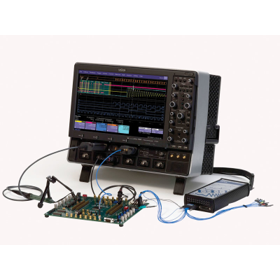
A Total Solution for Disk Drive Analysis
Maximum Performance
Teledyne LeCroy Disk Drive Analyzers (DDA) assist data storage design engineers by integrating tools that improve the time to market of new products and accelerate understanding and failure analysis on existing drives. Teledyne LeCroy continues that tradition with the DDA 7 Zi-A Series equipped with its powerful Disk Drive Analysis toolset. Capture, view, and analyze the wave shape of high-speed, complex drive signals with speed and integrity.
Data Storage applications are memory intensive as capturing multiple sectors or a complete track of data can be important in troubleshooting a design or characterizing media.
The X-Stream II architecture enables fast and accurate measurements and analysis of disk drive signals. Memory can be extended to 128 Mpts/Ch (256 Mpts/Ch on 2 Ch) using Option L. Both the DDA 760Zi and DDA 735Zi offer the convenience of selectable 50 Ω or 1 MΩ inputs. The standard 20 Mpts of waveform memory and 40 GS/s capture on two channels, means multiple drive sectors can be acquired at once.
Long Memory and Flexibility in Finding Problems Acquire a head signal up to 6 GHz, and then QuickZoom it from the front panel. The DDA copies and expands the drive signal automatically. Simply scroll horizontally and vertically to examine any sector. Multiple zooms let you view up to eight separate areas of the head signal; each zoom comes in a distinct color. Disk drive parameters let you characterize the pulse width variation or signal-to-noise ratio across a region. Failure Analysis engineers can store and recall golden waveforms and panel setups to compare problem drives with the known good drives. Analog-to-digital converters running at speeds up to 40 GS/s ensure the right sensitivity to measure today’s high-speed read channels. In every DDA, you can run your customer-developed scripts to view the captured signal with the filters matched to your channel and media. Custom user scripts can be created in MATLAB, Visual Basic, Excel or other formats.
Exceptional Trigger and Sequence Performance
The DDA’s disk triggers allow you to set up a series of events in the signal that then cause a trigger. For example, qualify the signal on the index signal and then capture all the sectors of information on the track. As memory is increased in the DDA, more sectors can be captured, with up to 50 picosecond/sample time resolution. Up to 15,000 sectors of data can be gathered with the DDA 7 Zi-A analyzers. An optional capability, Streaming Sequence, uses the X-Stream II and the fast hardware architecture of the DDA to streamup to 300,000 segments of data to memory; all taken at a high trigger rate.
Natural Graphical Interface
One press on the DDA menu takes you directly to the Disk Drive Analyzer features. The familiar controls on the front panel, coupled with a natural, context-sensitive graphical user-interface, react quickly to your commands. Functionality is exactly where you expect it to be.
The DDA 7 Zi-A provides one button access to all the tools needed to accurately debug and analyze disk drive operation.
The DDA 7 Zi-A features: 31 custom parameters
4 specific drive trigger
Sector
Servo Gate
PES trigger
Read Gate Trigger
Advanced drive analysis tools
Advanced Disk Drive analysis tools capabilities include:Head Filter Equalizer emulation
Channel Emulation
SAM Histograms
Plot of SAM values
PES runout analysis
Analog Compare
Simultaneously connecting low-speed signals, like index and servo gate, and high-speed signals, like read channels has never been easier. With integrated 50 Ω and 1 MΩ inputs on all models, there is no longer a need for expensive adapters.
MS-500 : 500 MHz, 18 Channels, 2 GS/s, 50 Mpts/ch Mixed Signal Oscilloscope Option
MS-500-36 : 250 MHz,36 Ch,1 GS/s,25 Mpts/ch (500MHz,18 Ch,2 GS/s,50 Mpts/ch Interleaved) Mixed Signal Option
MS-250 : 250 MHz, 18 Channels, 1 GS/s, 10 Mpts/ch Mixed Signal Oscilloscope Option
DDAZi-A-M-64 : 64 Mpt/Ch (128 Mpt/Ch Interleaved) Memory Option for DDA Zi-A.
DDAZi-A-L-128 : 128 Mpt/Ch (256 Mpt/Ch Interleaved) Memory Option for DDA Zi-A.
WPZi-500GB-HD : Upgrade from standard size hard drive to 500 GB hard drive
WPZi-500GB-RHD-02 : Additional 500 GB Hard Drive for WPZi. Includes Windows 7 OS, LeCroy oscilloscope software and critical scope operational file duplicates.
WPZi-8-UPG-32GBRAM : 8 GB to 32 GB CPU RAM Upgrade Option
GPIB-2 : IEEE 488 GPIB Interface
WPZi-PWR : Power Analysis Option for WP 7 Zi
WPZi-USB2-HSICbus D : USB 2.0 HSIC Decode Option
WPZi-VBA : Vehicle Bus Analyzer Bundle Includes CAN TDM, CAN Symbolic, FlexRay TDP, LIN TD and Protobus MAG.
WPZi-DigRFV4bus D : DigRF V4 Bus Decode option for WavePro Zi series
WPZi-Manchesterbus D : Manchester Bus Decode Option for WavePro Zi
WPZi-ENETbus D : ENET Bus Decode Option for WavePro Zi
WPZi-SpaceWirebus D : SpaceWire Decode Option for WavePro 7Zi series
WPZi-SATAbus D : SATA Decode option for WavePro Zi Supports SATA Gen 1, 2, and 3.
WPZI-UNIPRObus D : MIPI UniPro Protocol Decoder Software Option
WPZi-CAN FDbus TDM : CAN FDbus Trigger, Decode & Measure/Graph Option for WavePro Zi
WPZi-CANbus TDM SYMBOLIC : CANbus Trigger, Symbolic Decode & Measure/Graph Option for WavePro Zi Oscilloscopes
WPZi-CAN FDbus TDM SYMBOLIC : CAN FDbus Trigger, Symbolic Decode & Measure/Graph Option for WavePro Zi Oscilloscopes
WPZi-1553 TD : MIL-STD-1553 Trigger and decode option for WavePro Zi
WPZi-ARINC429bus DSymbolic : ARINC 429 Bus Symbolic Decode option for WavePro Zi
WPZi-AudioBus TD : AudioBus trigger and decode for WavePro 7Zi
WPZi-AudioBus TDG : AudioBus trigger, decode, and graph for WavePro 7Zi
WPZi-CANbus TD : CAN Bus Trigger & Decode Option for WavePro Zi Series Oscilloscopes
WPZi-CANbus TDM : CAN Bus Trigger, Decode, and Measure Option for WavePro Zi Series Oscilloscopes
WPZi-DigRF3Gbus D : DigRF 3G Bus Decode option for WavePro Zi
WPZi-DPHYbus D : D-PHY Bus Decode option for WavePro Zi
WPZi-FlexrayBus TD : FlexRay Bus Trigger & Decode Option for WavePro Zi Series Oscilloscopes
WPZi-DPHYbus DP : MIPI D-PHY CSI-2, DSI Bus Decode and Physical Layer test option for WavePro 7Zi series
WPZi-FlexRayBus TDP : FlexRay Bus Trigger, Decode, and Physical Layer Test Option for WavePro Zi Series Oscilloscopes
WPZi-HSPT : 100 Mb/s to 3.125 Gb/s High Speed Serial Trigger Option for 4-6 GHz Oscilloscopes & Disk Drive Analyzer
WPZi-I2Cbus TD : I2C Bus Trigger & Decode Option for WavePro Zi Series Oscilloscopes
WPZi-MPHYbus D : MIPI M-PHY Bus Decode option for WavePro 7Zi series
WPZi-LINbus TD : LIN Bus Trigger & Decode Option for WavePro Zi Series Oscilloscopes
WPZi-MSPT : 100 Mb/s to 1.25 Gb/s Medium Speed Serial Trigger Option for 2.5-3.5 GHz Oscilloscopes and Disk Drive Analyzers
WPZi-PCIEbus D : PCI Express (Gen 1.x, 2.0, and 3.0) Protocol Link Layer Decode Annotation for WavePro 7 Zi Series Oscilloscopes and Analyzers
WPZi-MPHYbus DP : MIPI M-PHY Bus Decode and Physical Layer test option for WavePro 7Zi series
WPZi-PROTObus MAG : Serial Debug Toolkit – Measure Analyze Graph for WavePro Zi Compatible with I2C, SPI, UART, CAN, LIN, FLX, D-PHY, DigRF 3G, DigRF v4, ARINC 429, MIL-STD-1553
WPZi-ProtoSync : Decode Annotation and Protocol Analyzer Software Synchronization Option for WavePro Zi
WPZi-ProtoSync-BT : Decode Annotation and Protocol Analyzer + Bit Tracer Software Synchronization Option for WavePro Zi
WPZi-SPIbus TD : SPI Bus Trigger & Decode Option for WavePro Zi Series Oscilloscopes
WPZi-UART-RS232bus TD : UART and RS232 Bus Trigger & Decode Option for WavePro Zi Series Oscilloscopes
WPZi-USB2bus D : USB 2.0 Bus Decode option for WavePro Zi
WPZi-USB3bus D : USB 3.0 Decode option for WavePro Zi Supports USB 3.0, 2.0, 1.x
WPZI-SENTbus D : SENT Bus Decode Option for WavePro Zi
WPZi-DFP2 : Digital Filter Software Package for WavePro Zi Series
LSIB-1 : High speed PCIe Gen1 x4 digitizer output for LeCroy oscilloscope. Half-height card
LSIB-HOSTBOARD : PCI Express x4 Host Interface Board for desktop PC
LSIB-HOSTCARD : PCI Express x1 Express Card Host Interface for laptop Express Card slot
LSIB-CABLE-3M : PCI Express x 4 3-meter cable with x4 cable connectors included
LSIB-CABLE-7M : PCI Express x 4 7-meter cable with x4 cable connectors include
QPHY-BroadR-Reach : QualiPHY Enabled BroadR-Reach Compliance Software Option. Requires either SDA2 or JTA2
QPHY-MIPI-DPHY : QualiPHY Enabled MIPI DPHY Compliance Software Option
WPZI-DDR2-TOOLKIT : DDR2 and LPDDR2 Debug Toolkit for WavePro Zi Oscilloscopes
WPZI-DDR3-TOOLKIT : DDR3, DDR3L, LPDDR3, DDR2, and LPDDR2 Debug Toolkit for WavePro Zi Oscilloscopes
WPZI-UPG-DDR3-TOOLKIT : DDR3, DDR3L, LPDDR3, DDR2, and LPDDR2 Debug Toolkit Upgrade for WavePro Zi Oscilloscopes
QPHY-MIPI-MPHY : QualiPHY Enabled MIPI M-PHY Compliance Software Option
QPHY-DDR2 : QualiPHY Enabled DDR2 Compliance Software Option
QPHY-DDR3 : QualiPHY Enabled DDR3, DDR3L and LPDDR3 Compliance Software Option
QPHY-ENET : QualiPHY Enabled Ethernet 10/100/1000BT Compliance Software Option
QPHY-HDMI : QualiPHY Enabled HDMI Compliance Test Software
QPHY-LPDDR2 : QualiPHY Enabled LPDDR2 Compliance Software Option
QPHY-PCIe : QualiPHY Enabled PCIe Gen1 and Gen2 Compliance Software Option
QPHY-SATA-TSG-RSG : QualiPHY Enabled SATA (PHY, TSG, RSG, and OOB) Compliance Software Option
QPHY-USB : QualiPHY Enabled USB 2.0 Compliance Software Option
QPHY-UWB : QualiPHY Enabled WiMedia UWB Compliance Software Option
ENET-2ADA-BNCSMA : Adapter Set- 2 BNC/M to SMA/F
ENET-2CAB-SMA018 : Cable Set- 2 SMA-SMA 18 inches
ENET-2CAB-SMA036 : Cable Set- 2 SMA-SMA 36 inches
DDAZi-CompleteLinQ : Bundle – Multi-Lane SDA LinQ Framewk, incl. Eye, Jitter, Noise, Xtalk Meas, w/EyeDrII & VirtualProbe
DDAZi-CrossLinQ : Multi-Lane Serial Data Analysis LinQ Framework, Eye, Jitter, Noise and Crosstalk Measurements
DDAZi-Crosstalk : Single-Lane Serial Data Analysis Framework, Eye, Jitter, Noise and Crosstalk Measurements
WPZI-PAM4 : PAM4 Serial Data Analysis, Eye, Jitter and Noise Measurements
DDAZi-LinQ : Multi-Lane Serial Data Analysis LinQ Framework, Eye and Jitter Measurements
WPZi-EYEDRII-VP : Bundle – EyeDrII and VirtualProbe Toolkits
WPZi-EYEDRII : Signal Integrity Toolkit – Channel & Fixture De-embedding/Emulation, Tx/Rx Equalization
WPZi-VIRTUALPROBE : Advanced De-embedding, Emulation and Virtual Probing Toolkit
WPZi-SPECTRUM : Spectrum Analyzer and Advanced FFT Option for WavePro Zi Series
WPZi-EMC : EMC Pulse Parameter Software Package for WavePro Zi Series
KYBD-1 : Keyboard, USB
WPZi-HARDCASE : Hard carrying case for all WavePro Zi Series oscilloscopes
WPZi-SOFTCASE : Soft carrying case for all WavePro Zi Series oscilloscopes
RACKMOUNT-1 : Rack-mount accessory for converting a WavePro Zi series oscilloscope to an 8U rack-mounted package
TTL-AUX-OUT : TTL Auxiliary output adapter for 7Zi and 8Zi oscilloscopes
Rise-Time-Filter-100ps : PSPL Rise Time Filter – PSPL Part Number 5915-110-100ps
Rise-Time-Filter-150ps : PSPL Rise Time Filter – PSPL Part Number 5915-110-150ps
20dB-SMA-Attenuator : 20 dB SMA Attenuators
Zi-8CH-SYNCH : HW Kit to allow combination of channels from two Zi or Zi-A oscilloscopes. Allows combination of all channels from two oscilloscopes (8 channels total) or combination of all 20-30 GHz channels from two 20-30 GHz 8Zi or 8Zi-A oscilloscopes (4 channels total), or combination of 45 GHz channels
WPZi-AORM : Advanced Optical Recording Measurement Package for WavePro Zi Series
PK400-0 : Extra Large Gripper Probe Set . Includes 22 probes
PK400-1 : Large Gripper Probe Set for 0.10 inch (2.54mm) pin pitch. Includes 10 probes with color coded leads
PK400-2 : Medium Gripper Probe Set for 0.04 inch (1.0mm) pin pitch. Includes 10 probes with color coded leads
PK400-3 : Small Gripper Probe Set for 0.008 inch (0.2 mm) pin pitch. Includes 10 probes with color coded leads
MSO-MICTOR : 36 Channel Mictor Connector for MS Series (Includes 1 MSO-MICTOR-SHROUD)
MSO-3M : 18 Pin 3M Interface cable MSO-3M (Mates with 3M part number 2520-6002)
MSO-DLS-36 : 16" Digital Lead Set, D18-D35
TF-ENET-B : 10/100/1000BaseT Ethernet Test Fixture
TF-HDMI-3.3V-QUADPAK : HDMI Pull-Up Terminator Quad Pack – For Use with the Wilder-Tech HDMI-TPA-P Plug Test Adapter
TF-SATA-C-Kit : SATA Compliance Test Kit
TF-USB-B : USB 2.0 Compliance Test Fixture
TF-MIPI-MPHY-DUALPAK : MIPI M-PHY input offset adapter dual pack
There are no reviews for this product at the moment
No current Alternatives.
You may find Alternatives in category.