No Current Sellers for Yokogawa DLM4038
Sign Up/Login to get notified when someone has one for sale.
Sign Up/Login to get notified when someone has one for sale.
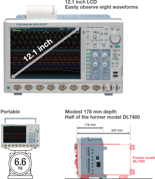
The DLM4000 is a unique to the industry eight-channel mixed-signal oscilloscope suitable to test and debugging applications in the embedded systems, power electronics, mechatronics, and automotive sectors. Available in both 350 MHz and 500 MHz models, the 2.5 GSa/sec DLM4000 features eight analog input channels. The eighth input channel features Flex MSO which converts to a 8-bit logic analyzer at the push of a button; add sixteen additional logic analyzer inputs as an option, for 24-bit logic analysis. Advanced measurement and analysis features such as power analysis and serial-bus analysis, digital filtering, user-defined math, and super-long record lengths (up to 250 Mega Points) make the DLM4000 a super powerful engineering tool. High-resolution 12.1-inch LCD display, compact landscape format, ergonomic and friendly user-interface make it easy to use.
Motor control & inverter circuit development
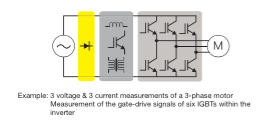 Key to efficient and reliable high-performance electric motors is the modern inverter design, or ‘Intelligent Power Module’. Multi-channel, high-speed waveform measurement is an absolute necessity. Four channels are simply not enough. Boasting eight true analog inputs, the DLM4000 empowers today’s engineer with a convenient and comprehensive measurement system.
Limitation of 4 ch scope: Whole-system measurement is impossible with a four-channel scope; the real difficulty is measuring the timing between IGBT gate signals within the inverter. Voltage and current measurements between 3 phases and the IO of the motor driver IC is a very challenging test with a four-channel scope. The truly practical solution is an eight-channel MSO.
Electronic control unit & mechatronic test
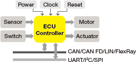 Numerous I/O analog, digital, and serial-bus waveforms surrounding the Electronic Control Unit (ECU) must be measured. The DLM4000 offers ample channel-count and architecture to monitor eight analog channels and up to 24-bits of logic input while simultaneously performing protocol analysis such as UART, I²C, SPI, CAN, CAN FD, LIN and FlexRay. The DLM4000 can speed up the R&D process when four channels are not enough.
Limitation of 4 ch MSO: The additional logic inputs of a four-channel MSO mixed-signal oscilloscope provides enough channels, but this method has a blind-spot. Digital waveform analysis using logic inputs alone cannot reveal anomalies such as voltage drift, noise, distortion or ringing, and measure risefall times. ECU testing requires stringent examination of all digital waveforms- and analog input channels are the best tool for the job.
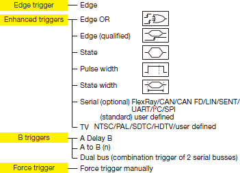 When just a specific event or abnormal waveform needs to be captured, the flexible and reliable triggering of the DLM4000 is the solution. In addition to basic trigger functions such as Edge, State, and Pulse Width- Advanced trigger types are provided, including Edge OR between multiple channels, Serial Bus trigger in which A combination of two bus signals is possible, or an A and B combination of different trigger types.
The two advantages of a long waveform memory are the abilities to capture for long periods of time and to maintain high sample rates. Thus achieving higher effective measuring bandwidths for all time base settings.
Measuring time = Memory length / Sample rate
With the maximum memory installed (/M3 option), in single shot mode, a 10 kHz signal lasting for more than one hour can be captured. The same memory can capture a 200 millisecond signal at a sampling rate of 1.25 GS/s.

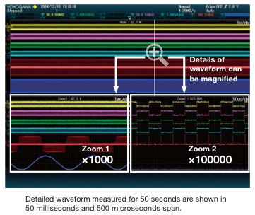
Two fully independent zoom windows
Enabling two fully independent zoom windows allows users to analyze the cause and effect of abnormal behaviors over all input channels. Users can also view and compare the details and timing of different serial buses operating at different speeds.
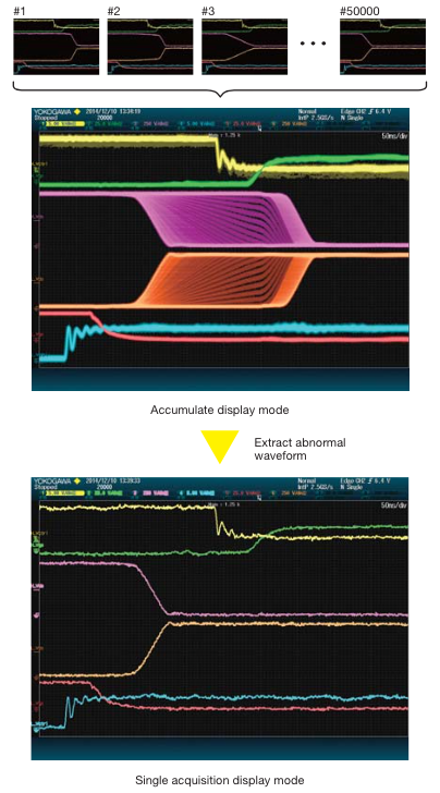
The DLM4000 can capture and replay up to 50,000 individual acquisitions (/M3 option). These can be displayed one at a time or as an accumulation. Using the search and measurement functions, abnormal signals can therefore be quickly isolated, analyzed and precisely categorized without needing to carefully configure triggers to capture rare events.
History Search Function
Search up to 50,000 waveform history records based on detailed search parameters using the history search function.

Replay Function
Automatically play back, pause, fast forward, and rewind waveform history records.

709820 -G2 User defined math
-G3 Power supply analysis function
-G4 Power supply analysis function (includes G2)
-F1 UART trigger and analysis
-F2 I²C + SPI trigger and analysis
-F3 UART + I²C + SPI trigger and analysis
-F4 CAN + LIN trigger and analysis
-F5 FlexRay trigger and analysis
-F6 FlexRay + CAN + LIN trigger and analysis
-F7 CAN + CAN FD + LIN trigger and analysis
-F8 FlexRay + CAN + CAN FD + LIN trigger and analysis
-F9 SENT trigger and analysis
-X1 F4 -> F7 or F6 -> F8 (adds CAN FD)
There are no reviews for this product at the moment